Open topic with navigation
Controlled Stop
In a controlled stop, drive motion is brought to a standstill in a controlled manner. The drive commands a zero velocity from the motor. The motor decelerates at the prescribed deceleration value (CS.DEC ).
A controlled stop can occur in three ways:
- The user configures a programmable digital input to mode 13 using DINx.MODE. For example, if DIN1.MODE 13 is applied, digital input 1 is set to controlled stop.
- Either a controller or the user (through the WorkBench terminal window) initiates a software disable (DRV.DIS) command .
- A fault initiates a controlled stop from the drive. See Fault and Warning Messages for the faults which initiate a controlled stop.
The controlled stop mechanism is activated in the following cases:
- DRV.DISMODE = 2 and user executes DRV.DIS from the terminal or WorkBench disable buttons.
- DRV.DISMODE = 2 and user executes DRV.DIS from a fieldbus connected to the drive.
- A fault occurs which has a controlled stop (CS) reaction. After the CS is executed, the drive disables.
- A digital input mode (DINx.MODE) is set to 13. If the digital input state changes (active high or low according to DINx.INV) the CS is executed, and then the drive disables.
- HW limit switch: A digital input is defined as a positive (negative) limit switch (DINx.MODE 18 or 19). When the limit switch is met, the CS mechanism starts running. In this case, the parameter DRV.DISTO is not active.
- SW limit switch: SWLS defines an active SW limit. When the limit is met, the CS mechanism starts running. In this case, the parameter DRV.DISTO is not active.
Use the drive CS parameters to configure a controlled stop as follows:
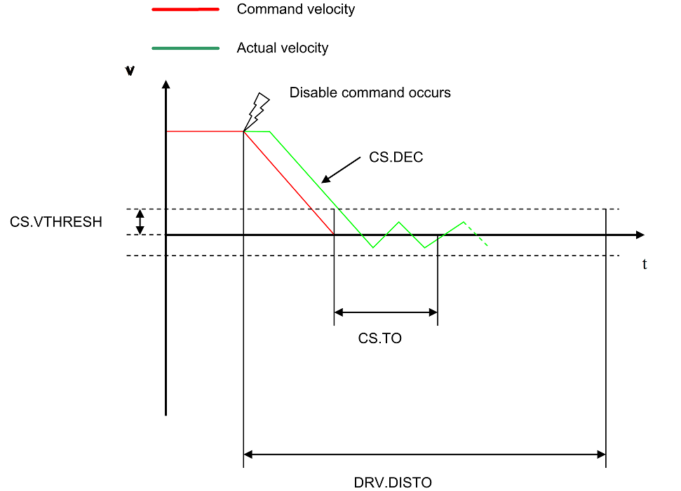
- CS.DEC: Deceleration ramp that is used for disable.
- CS.VTHRESH: Velocity 0 threshold. The motor shaft is considered as stopped as soon as the actual velocity (filtered through a 10 Hz filter, such as VL.FBFILTER) is within ± CS.VTHRESH.
- CS.TO: Velocity 0 time. The actual velocity must be consecutively within 0 ± CS.VTHRESH for the time CS.TO, before the drive completes the CS process. This value is used since the motor can overshoot out of the VEL0 window depending on the gains, deceleration ramp, motor inertia and so on.
- DRV.DISTO: time out. This parameter sets an overall and independent running check as to whether or not the drive can achieve the disable state. If the VEL0 window set in step 3 is too small, it is possible that the drive may never reach the end of the CS process. The DRV.DISTO parameter and functionality addresses this issue by disabling the drive after the DRV.DISTO time elapses, even if the CS process did not end.
Controlled Stop Diagram
When configuring the controlled stop feature, please note the following:
- If the HW limit switch is active and any of the other CS activated, the only difference will be that in this case the DRV.DISTO will limit the time before disabling the drive.
- If the value of DRV.OPMODE of the drive is current mode, the drive will not execute the CS but instead stop immediately.
- Set DRV.DISTO to an appropriate value that will allow the motor to decelerate from any velocity to 0 with DRV.DEC. This value must also allow the motor to afterwards remain within VL.FB for CS.TO consecutively within 0 ± CS.VTHRESH.
The drive issues a fault FF703
in case that the DRV.DISTO counter expires during a controlled stop procedure.
Related Parameters and Commands
CS Parameters
CS.STATE : Reads the current state of controlled stop process (0 = controlled stop is not occurring. 1 = controlled stop is occurring).
DIN1.MODE TO DIN7.MODE
DRV.DIS
DRV.DISTO
DRV.DISMODE
Related topics:
Emergency Stop
Digital Inputs and Outputs
Fault and Warning Messages
|
|
Copyright © 2015 Kollmorgen™
|
|

|
Open topic with navigation


